
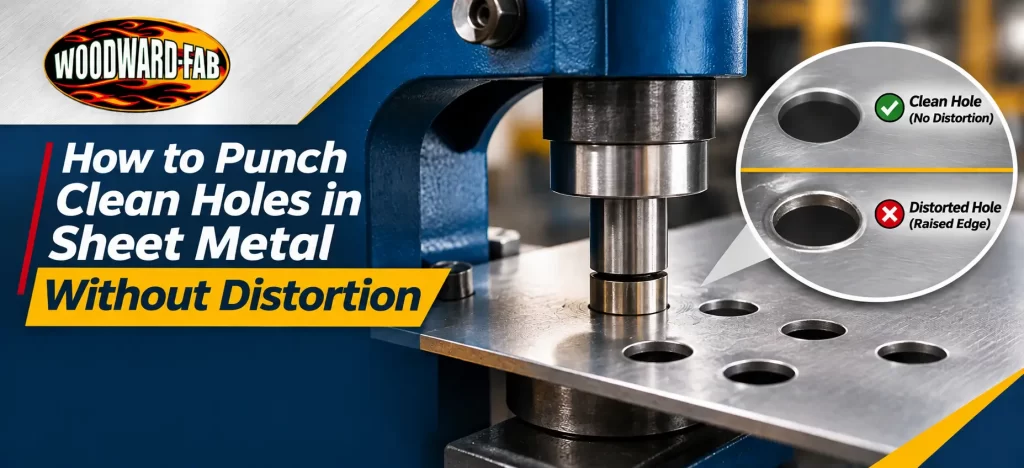
A punched hole may meet its diameter specification and still cause problems during assembly. Raised edges, warped panels, excessive burrs, and inconsistent hole locations can affect fastener installation, weld fit-up, and the appearance of finished components.
For industrial fabrication shops, these defects create more than cosmetic issues. They can lead to additional deburring, rejected parts, and unnecessary production downtime.
Understanding how to punch clean holes in sheet metal without distortion begins with tooling clearance, material support, punch alignment, and the right equipment.
Use properly matched punch-and-die tooling, maintain the recommended clearance, support the sheet close to the cutting area, and prevent movement during punching. Inspect tool condition, confirm material thickness, and test the setup before production.
Why Does Sheet Metal Distort During Punching?
Punching removes material through a shearing action. As the punch enters the sheet, the metal initially deforms before the cutting edges create a fracture through its thickness.
When tooling and support conditions are unsuitable, the surrounding sheet may bend, stretch, or develop an uneven edge.
- Insufficient support: The sheet flexes during force application.
- Incorrect die clearance: Burrs and edge deformation may increase.
- Worn tooling: Cutting forces become less consistent.
- Poor hole placement: Material near edges or adjacent features may deform.
Thin panels are particularly sensitive because they offer limited resistance to bending. The objective is to control how the material behaves throughout the punching cycle.
What Does a Clean Punched Hole Look Like?
A properly produced hole should have a consistent diameter, suitable roundness, minimal surrounding distortion, and an acceptable edge condition.
Punched edges typically contain rollover, a sheared section, a fractured section, and a burr. Their proportions depend on material properties and cutting conditions.
Inspect five important characteristics:
- Hole diameter against the drawing tolerance
- Hole position relative to the part datum
- Burr height and finishing requirements
- Flatness around the punched opening
- Cracks, tearing, or irregular fractures
Inspection criteria should reflect the finished component’s intended use, especially for parts requiring accurate assembly or repeatable fit-up.
How Punch-to-Die Clearance Affects Hole Quality
Punch-to-die clearance is the gap between the punch cutting edge and die opening. It allows material to shear and fracture as the punch passes through the sheet.
Clearance that is too tight can increase cutting forces and tool wear. Excessive clearance may contribute to greater rollover, burr formation, and hole deformation.
(Die opening diameter – Punch diameter) / 2
Example: A 0.500-inch punch and a 0.520-inch die opening produce 0.010 inch of clearance per side.
This is a geometry example, not a recommended clearance for every material. Use the tooling manufacturer’s specifications for the material and thickness being punched.
How to Prevent Sheet Metal From Bending Around a Hole
Support the Material Close to the Cutting Area
Use an appropriate die and workholding arrangement to support the sheet near the intended hole. Large panels may require additional external support to prevent bending under their own weight.
Prevent Movement During Punching
Suitable clamps, guides, hold-downs, or stripping arrangements can help maintain position. The material should not slide or lift unexpectedly during the operation.
Inspect Tooling Alignment
Misalignment may cause uneven contact, irregular edges, and premature tool wear. Follow the equipment manufacturer’s inspection and adjustment procedures.
Common Sheet Metal Punching Defects and Solutions
| Defect | Possible Cause | What to Check |
|---|---|---|
| Excessive burrs | Tool wear or unsuitable clearance | Cutting edges and die clearance |
| Raised metal around hole | Insufficient material support | Hold-down and die support |
| Irregular hole | Misalignment or shifting material | Tool alignment and fixtures |
| Cracks near hole | Material condition or spacing | Material grade and hole location |
| Inconsistent hole position | Poor locating method | Stops, guides, and repeatability |
These are diagnostic starting points. Multiple conditions can contribute to the same defect.
How Material Thickness Changes Punching Requirements
The force required for punching depends on the cut perimeter, material thickness, and material shear strength.
Cutting perimeter x material thickness x material shear strength
For a round hole, cutting perimeter equals pi x hole diameter.
For example, a 0.5-inch hole in 0.060-inch sheet with an assumed shear strength of 40,000 psi requires approximately 3,770 pounds-force, or 1.89 US short tons-force, using this simplified formula.
Actual requirements depend on material properties, tooling, clearance, and process conditions. Verify equipment ratings and operating limits before selecting a machine.
Mild Steel, Stainless Steel, and Aluminum
Mild steel is widely used in brackets, enclosures, and general fabrication. Stainless steel can require greater punching force, depending on its grade and condition. Softer aluminum alloys may be susceptible to local deformation if material support is inadequate.
Always verify actual thickness and material grade rather than relying on gauge number alone.
Woodward Fab Tools for Sheet Metal Hole Punching
Choosing the correct tool depends on hole diameter, material thickness, required access, and production frequency. The following products address different fabrication requirements.

Woodward Fab Punch and Flanger Combo
For automotive panels, patch work, and lighter sheet metal applications, the WFPF combines hole punching and edge flanging in one hand-operated tool.
- 3/16-inch punch diameter
- Punches up to 18-gauge mild steel
- Flanges up to 20-gauge mild steel
- 1/16-inch step flanger
- 11-inch overall length
- Spring-return handle
The WFPF is particularly relevant when creating small holes near panel edges. Its published punch-center reach is approximately 1/4 inch from the edge, so it is not intended for holes located deep inside large panels.

Woodward Fab WFP20 Manual Punch
For fabrication jobs requiring a wider range of hole sizes and greater material capacity, the WFP20 provides a gear-driven manual punching arrangement.
- 6.25-inch throat depth
- Punches up to 3/16-inch-thick steel
- Gear-drive cam mechanism
- Includes punches from 1/8 to 5/8 inch
- Published weight: 200 pounds
This configuration may be more appropriate than a small hand punch when the work requires greater reach or thicker steel, provided the selected hole size and material fall within the manufacturer’s rated limits.
This kit is useful for limited-capacity punching tasks, but the published product listing currently identifies it as out of stock. Confirm availability before recommending it for immediate purchase.

Woodward Fab 1-Inch Dimple Die
Some fabrication projects require a formed or flared opening rather than a conventional flat punched hole. The PF4A is designed for punch-and-flare sheet metal applications.
- 1-inch nominal die size
- Up to 1/16-inch mild steel
- Up to 14-gauge aluminum
- Requires a 1/2-inch pilot hole
- Draw-bar bolt included
Why Hole Spacing and Edge Distance Matter
A clean punch cannot compensate for a poorly designed hole pattern. Holes positioned too close to an edge or adjacent opening can leave insufficient material to resist deformation.
Review the hole-center distance from the material edge, the spacing between neighboring holes, and the remaining material between openings.
Minimum acceptable spacing depends on material properties, thickness, hole geometry, and tooling requirements. There is no single spacing rule that applies to every fabrication process.
Production Checklist: Before Punching 100 Parts
A setup that produces one acceptable component does not automatically guarantee consistent results across a production batch.
- Verify the material grade and thickness.
- Confirm punch and die compatibility.
- Inspect cutting edges for wear or damage.
- Check alignment and material support.
- Verify stops, guides, and fixtures.
- Inspect the first completed part.
- Establish periodic quality checks.
Monitor recurring burrs, dimensional variation, and tool wear. Recording these issues helps identify process changes before they affect a larger batch.
Frequently Asked Questions
How do you punch thin sheet metal without bending it?
Use matched punch-and-die tooling, support the sheet near the opening, prevent movement, and verify alignment and clearance before production.
Why do punched holes have burrs?
Burrs can form during the shearing and fracture process. Excessive burrs may indicate worn tooling, unsuitable clearance, or other setup problems.
Is punching better than drilling sheet metal?
Punching can be efficient for repeatable holes with suitable tooling. Drilling may be more practical for occasional holes or locations a punch cannot reach.
Can stainless steel be punched?
Yes, when the tooling and equipment are rated for the stainless steel grade, thickness, and required force.
What is the difference between a punch and a dimple die?
A conventional punch removes material to create a hole. A dimple die forms a raised or flared profile around an opening for a different finished geometry.
Better Hole Quality Starts Before the Punch Moves
Clean sheet metal punching depends on controlling clearance, material support, alignment, tooling condition, and inspection requirements.
For industrial fabrication shops, these controls can reduce unnecessary finishing work, improve component fit-up, and support more consistent production.
Whether you manufacture brackets, equipment enclosures, automotive panels, or custom metal components, match the punching equipment to the material and finished-part requirements.
Find the Right Sheet Metal Punching Tool
Explore Woodward Fab punch and flange tools, manual punches, and forming equipment for your fabrication needs.
Explore Punch and Flange Tools
Related Post:
- How to Roll Sheet Metal Into a Cylinder:Diameter, Thickness and Springback
- How to Select Welding Turning Rolls for Different Pipe Diameters and Loads
- Metalworking Tool Selection Guide: Match the Tool to the Fabrication Task
- How to Read a Sheet Metal Gauge Chart: Gauge, Thickness & Material Explained
- Sheet Metal Forming Methods: Deep Drawing, Flanging, Hemming & More